Automotive and Appliances: ULTRASONIC WELDING TO JOIN PLASTIC PARTS
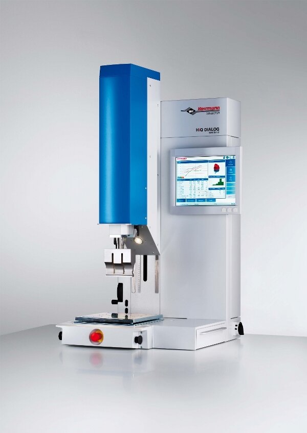
Short cycle times determine the rhythm of modern production, hence fast and economic assembly processes are needed. This explains the rise and success of the ultrasonic welding technology in recent years. The advantage: within seconds a high-strength, gas-and watertight bond is produced without any additives. Herrmann Ultraschall from Germany has been a specialist in ultrasonic welding equipment for nearly five decades.
In the production process for household appliances many parts need to be joined, like the display screen of the front panel or the two halves of the pump wheel. In the automotive sector, there are over 100 applications for ultrasonic welding, tail lights, instrument cluster, motor parts to name a few.
Ultrasonic welding delivers quality bonding at high production speeds and is therefore a good joining method for injection moulded polymer parts. Because the ultrasonic welding process requires low energy consumption, the thermal impact on the parts is minimal. Hard, amorphous plastics such as PC, PS, SAN, ABS and PMMA have very good transmission characteristics for ultrasonic waves. Semi-crystalline plastics such as PA, PP, PE and POM are best welded in the immediate near field of the sonotrode. Welded parts can be processed immediately after joining, so that ultrasonic welding units can be integrated easily into automation lines.
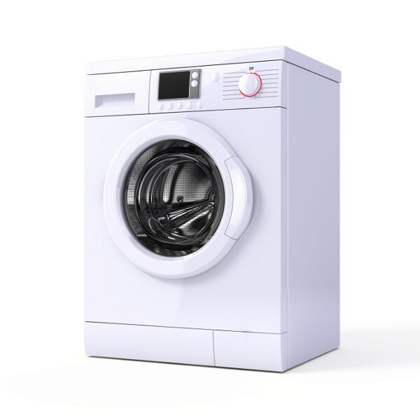
Figure 01:Parts for a washer are welded ultrasonically
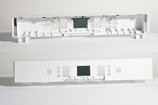
Figure 02: Front panel of washer
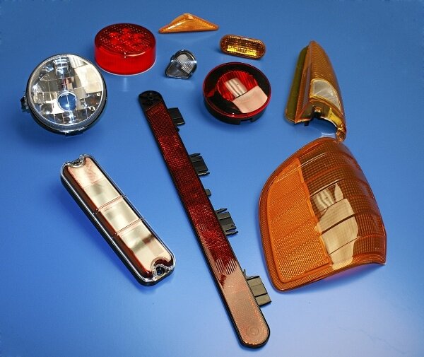
Figure 03: Automotive lights
Turning voltage into mechanical vibration
The ultrasonic process directs mechanical vibrations into the plastic assembly utilizing a specific frequency, amplitude, force and duration. The ultrasonic stack consists of generator, converter, transformation piece (called booster) and weld tool (called sonotrode). The generator converts voltage into high-frequency voltage. By using the piezoelectric effect, the converter changes the high-frequency voltage into ultrasonic waves (20 to 35 kHz). The sonotrode expands and contracts rapidly (20kHz means 20.000 movements per second), thereby introducing the mechanical vibrations into the joint area of the work piece. The vibrations cause friction in the joint area and start melting the material. A short cooling phase under pressure will ensure correct solidification. Since ultrasonic vibrations break up the molecular structure, the parts are tightly bonded, as if they were one piece.
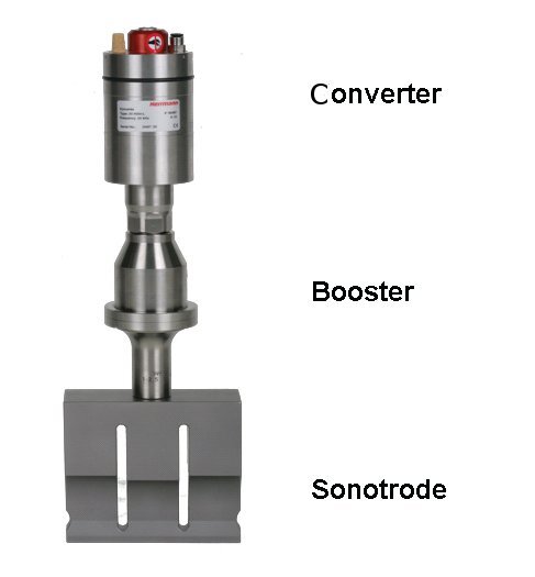
Figure 04:– mechanical vibrations cause the melting
It is all about the right joint design
The major advantage of ultrasonic technology is the specific energy input, which allows a precisely defined and temporally controlled melting. Through a special joint design the ultrasonic waves are focused directly into the joint zone. The joint design for injection moulded parts consists of suitable welding geometries with points or edges in the joining area. They are called energy directors and define the direction of the melt initiation. The contact points of the weld geometry prevent large-scale coupling.

Figure 05: joint design for ultrasonic welding
Good results in terms of strength, tightness and appearance can be achieved if the plastic parts are specifically designed for the ultrasonic process, including all procedural and material features. Herrmann Ultraschall is a German specialist for ultrasonic technology and focuses on sustainable consulting. Polish sales engineer Marcin Tomczyk explains: “We do not sell a mere machine but rather a complete solution for our customers’ applications. This starts in the planning phase of the injection moulded parts where we advise the engineers of the right joint design."

Figure 06: Marcin Tomczyk
Weld force switching for desired joining velocity.
A good weld can be displayed visually. The graphical representation of the welding power, joining velocity and weld force permits exact statements about the quality of the joining process.
A rapid and linear slope of the joining velocity curve (blue) is desired for even melt built-up and good, repeatable results. This avoids unnecessary loads on the part and guarantees reproducibility of the welding process.
The controlled switchover to a different weld force in mid-process, as available in the HiQ DIALOG machine, ensures the linear and smooth slope of the curve and therefore helps to optimize the weld.
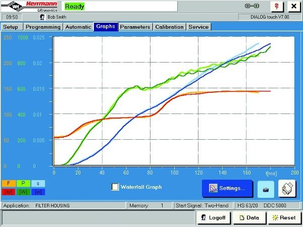
Figure 07: ideal joining velocity: blue curve
Figure 08: Ultrasonic welder HiQ DIALOG for complex applications
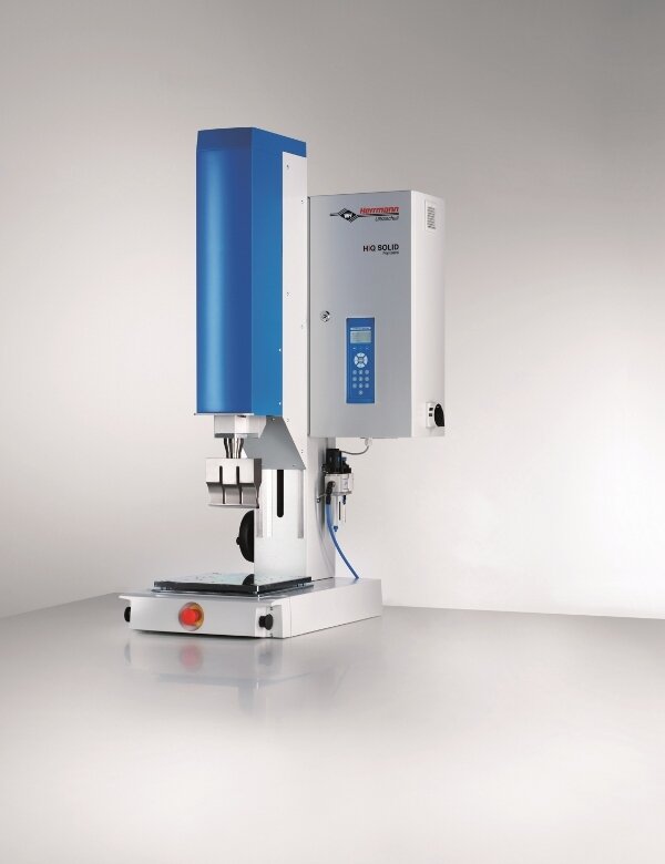
Figure 09: Ultrasonic welder SOLID – base model with three weld modi
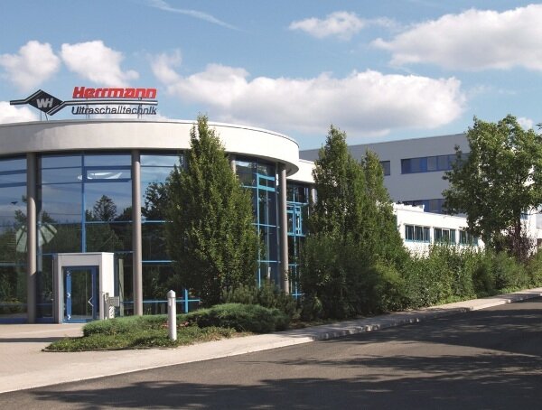
Figure 10: Headquarters Herrmann Ultraschall Germany
Herrmann Ultraschall with headquarters in Germany has 260 employees with subsidiaries in North America and China.
More info: www.herrmannultraschall.com